Absolute Encoder Connection Diagram
Minas E Series Wiring Connection Automation Controls Industrial Devices Panasonic

Library 26 Rotary Encoder On Stm32f4 Stm32f4 Discovery
Q Tbn And9gcskmzjcu9vpktmf9jdmo47raewmblafwqf0znqgkrha6fmosa Usqp Cau

Feedback Connections Jupiter

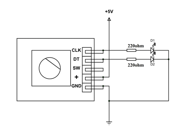
In Depth How Rotary Encoder Works And Interface It With Arduino

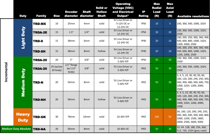
How To Select Apply And Integrate The Right Encoder For An Industrial Automation Application
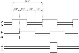
Typical Connections for Each Encoder A A A/ B B B / Z Z Z / 0 0 Encoder USB Conve rter Encoder Single Ended Line Driver Figure 2 Connection Diagram Single Ended Line Encoder Supply A A A/A/ BB B/ B/ ZZ Z/ Z/ V 0V V 0V Encoder USB Converter Encoder Differential Line Driver Output Figure 1 Standard Connection to.
Absolute encoder connection diagram. Absolute encoders generate information about position, angle, and rotation counts in typespecific angle steps For this, a unique code pattern is assigned to each angle increment The number of code patterns available per revolution determines the resolution Each code pattern forms a unique reference, and is therefore an absolute position. WIRING DIAGRAM Model RSW12UL Press and hold STOPthen press and 33 Linear Drive Disengaged (Arm 2) connections 34 Absolute Position Encoder Error, not getting position information from encoder Check the operator cable connections, then reprogram the limits 35. Introduction Selection guide 4 Measuring principles, accuracy 14 Mechanical design types and mounting Rotary encoders with stator coupling 16 Rotary encoders for separate shaft coupling 19 Shaft couplings 24 General mechanical information 27 Safetyrelated position measuring systems 30 Specifi cations Absolute rotary encoders Incremental rotary encoders.
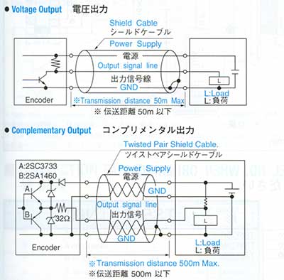
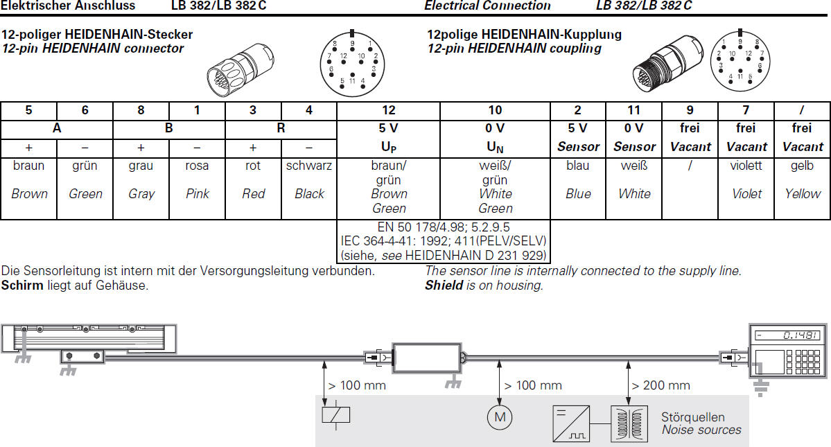
Wiring the Encoder Connecting the Connection Base To connect the connection base, proceed as follows Wiring diagram NOTE Shielded cables should be used for data transmission to avoid problems with electromagnetic interference The shieldi ng should be connected to ground at both ends of the cable. BiSSC Absolute Encoder, MasterInterface Reference Design for C00™ MCUs TI Designs TIDM1010 BiSSC Absolute Encoder, MasterInterface Reference Design for C00™ MCUs Description C00™ microcontroller (MCU) Position Manager technology offers an integrated solution to interface to the most popular digital and analog position sensors,. Assortment of heidenhain encoder wiring diagram A wiring diagram is a streamlined traditional photographic depiction of an electric circuit It reveals the parts of the circuit as simplified forms, as well as the power and signal connections in between the gadgets.
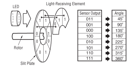
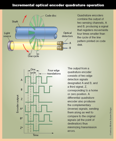
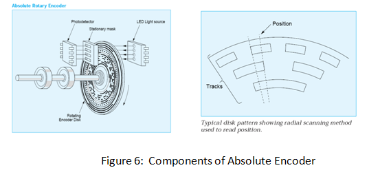
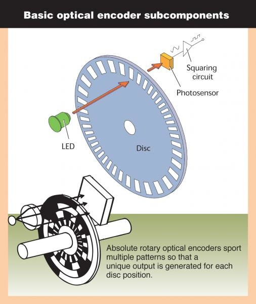
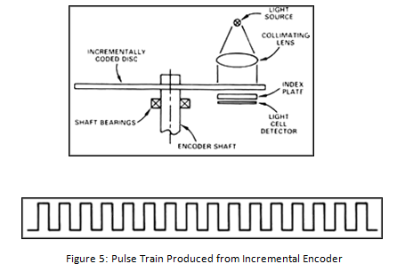
Encoders provide motion control systems information on position, count, speed, and direction As the encoder shaft rotates, output signals are produced, proportional to the distance (angle) of rotation The signal may be in the form of a square wave (for an incremental encoder) or an absolute measure of position (for an absolute encoder). Our EtherNet/IP™ Absolute Encoders are designed with an embedded EtherNet/IP switch and dual Ethernet ports to support linear networks and Device Level Ring topologies By providing auxiliary feedback directly through an EtherNet/IP network, these encoders eliminate the need for pointtopoint wiring. Absolute Encoders(MultiTurn) About Absolute encoder Absolute encoders output the absolute value of rotation anglesThe encoders are used for position control of servo motors mounted on machine tools or robotsAs shown in Figure 2, rotation slits are lined from the center on concentric circles.
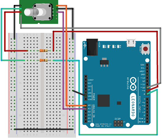
The absolute encoder gives us the exact position of the knob in degrees while the incremental encoder reports how many increments the shaft has moved Wiring As the wiring diagram shows you’ll need a servo motor Connect the Red wire of the servo motor to the external 5V supply, the Black/Brown wire to ground and the Orange/Yellow wire. Connecting absolute Encoders hardwired is a thing of the past as far as I'm concerned (depending on the resolution you require a fair few wiring cores as well as digital inputs) A Profibus DP based connection is the way to go for absolute Encoders and also allowes you to (flexibly) preset the Enocder with a reference value if need be. Absolute Rotary Encoders Safety 1512 7 3 Safety 31 Symbols Relevant to Safety 32 Intended Use Absolute rotary encoders detect the rotation angle —and, in the case of a multiturn absolute rotary encoder, the revolutions of the rotary encoder shaft—with high precision and resolution.
Get information about the communication protocols available with EPC's line of absolute encoders Tools for Specifying Your Encoder Get help answering some of the most frequently asked questions about encoders and motion control. Absolute Encoders Absolute Encoders retain your position data during loss of power They are excellent choices in systems that require failsafe operation Our magnetic encoders directly connect to DeviceNet™ for advanced functionality with reduced wiring cost. While if it is simultaneously given for 4 seconds, the encoder will come back to its absolute position 92 Accessories required for the programming of Synchronous Serial Encoders The encoder parameters can be modified by using a proper system For this purpose, Hohner suggests the following Function RESET Connector.
Absolute encoders Absolute encoder on the other hand indicates both the position and location of that position relative to the shaft rotation The encoder provides a unique word or bit for each incremental rotation Absolute encoders are the best choice for applications where exact positions to be known. EU Declaration of Conformity for Motors of the series DR263 DR280Possibly in connection with brake of the series BE as well as for FS02 and FS11 Possibly in connection with encoder of the series EI7, EI8, EK8, AK8, AH8, XK, XV, EV2, EV7, AV7, as well as for FS04 and FS11 0,08 MB 01/ 0,08 MB 01/ 0,08 MB 01/. EU Declaration of Conformity for Motors of the series DR263 DR280Possibly in connection with brake of the series BE as well as for FS02 and FS11 Possibly in connection with encoder of the series EI7, EI8, EK8, AK8, AH8, XK, XV, EV2, EV7, AV7, as well as for FS04 and FS11 0,08 MB 01/ 0,08 MB 01/ 0,08 MB 01/.
Encoder wiring schemes can be unique to each encoder and one should follow the diagram or pinout designated on the encoder datasheet Multichannel differential encoder wiring with commutation tracks can have up to 14 wires and miswiring can result in signal issues such as deformed pulses, low signal amplitude and shorted connections. FEN11 Absolute Encoder Interface User's Manual ID 3AFE PART 1. EU Declaration of Conformity for Motors of the series DR263 DR280Possibly in connection with brake of the series BE as well as for FS02 and FS11 Possibly in connection with encoder of the series EI7, EI8, EK8, AK8, AH8, XK, XV, EV2, EV7, AV7, as well as for FS04 and FS11 0,08 MB 01/ 0,08 MB 01/ 0,08 MB 01/.
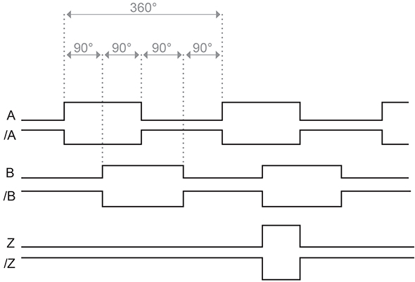
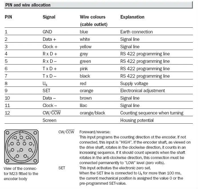
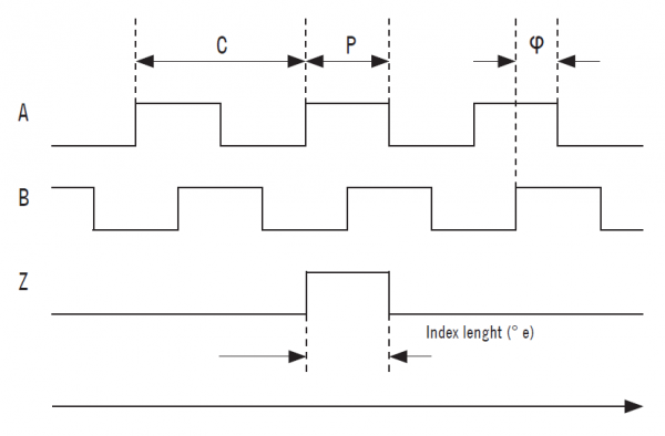
Timing diagram Connections V dd GND Sin Cos Timing diagram RMB28IE / RMF44IE – Incremental, Open Collector, NPN Low cost alternative for ball bearing encoders Power supply V dd = 5 V ±5 % Current consumption 35 mA (not loaded) Output signals A, B, Z Maximum output load mA Accuracy Typ ±05° Hysteresis 018° Resolution 3, 400, 500. The external (logic) connection of the function blocks must be performed by the user This includes, for example the axis number, the encoder number and the reference point number General state diagram for the acyclic block EncoderAdjustment (F8000) Fig 22. Absolute Encoder Multiturn PIN Signal Wire colours Explanation (cable outlet) 1 GND blue Earth connection 2 Data white Signal line 3 Clock yellow Signal line 4 R x D grey RS 422 programming line 5 R x D – green RS 422 programming line 6 T x D pink RS 422 programming line 7 T x D – black RS 422 programming line 8Us red Supply voltage.
A Gray code absolute rotary encoder with 13 tracks Housing, interrupter disk, and light source are in the top;. While if it is simultaneously given for 4 seconds, the encoder will come back to its absolute position 92 Accessories required for the programming of Synchronous Serial Encoders The encoder parameters can be modified by using a proper system For this purpose, Hohner suggests the following Function RESET Connector. ECI 4000 and EBI 4000 absolute inductive rotary encoders Duration 238 heidenhaintv 4,561 views 238 RESOLUTE™ true absolute optical linear and rotary (angle) encoder Duration 428.
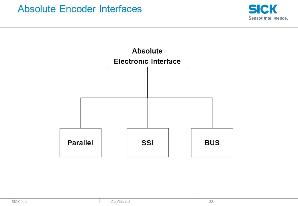
EAW Absolute Contacting Encoder (ACE™) Pin Output Code For ACE128 Bit/Pin correlation b7 b6 b5 b4 b3 b2 b1 b0 = p8 p7 p6 p5 p4 p3 p2 p1 A binary “1” denotes an “open” switch and a binary “0” denotes a “closed” switch Positions 0127 are seen by a clockwise rotation of the shaft Position p8 p7 p6 p5 p4 p3 p2 p1 Decimal Output. Absolute encoders transmit absolute position as a multibit digital word They can be connected using parallel wiring, fieldbus, or pointtopoint wiring The number of conductors needed for each type varies Learn more about absolute encoder communication protocols here Table 2 Absolute encoder wiring schemes Importance of Encoder Cable Quality. InstallationInstructions Bulletin842A Absolute Encoders IMPORTANT SAVE THESE INSTRUCTIONS FOR FUTURE USE Specifications Electrical CodeFormat Gray orNatural Binary CodeDirection CW or CCW Symmetry 40% to 60% Operating Voltage 10–32V DC Power Requirements 150mA @ 5V (no load) Max #ofSteps/Revolution 8192 Max # ofRevolutions 8192 Position Forming Time 05msec Delay on Power Up 1050msec.
4 Connection an Absolute Encoder The encoder is connected by a 4 pin A coded M12 connector for the power supply and two 4 pin, Dcoded M12 connector for Ethernet 41 2Connector Ethernet Powerlink 4 pin female, Dcoded Pin Number Signal Sketch on encoder view 1 Tx 2 Rx 3 Tx 4 Rx 42 Connector Power Supply. The external (logic) connection of the function blocks must be performed by the user This includes, for example the axis number, the encoder number and the reference point number General state diagram for the acyclic block EncoderAdjustment (F8000) Fig 22. Universal Digital Interface to Absolute Position Encoders TI Designs Design Features The TIDA reference design is an EMC • Universal Hardware to Interface With EnDat 22, compliant universal digital interface to connect to BiSS, SSI, and 4Wire or 2Wire HIPERFACE DSL absolute position encoders like EnDat 22, BiSS®, Encoders.
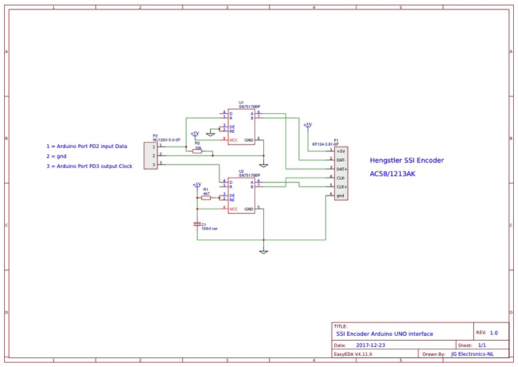
The output of an absolute encoder indicates the current shaft position, making it an angle transducer The output of an incremental encoder provides information about the motion of the shaft, which typically is processed elsewhere into information such as position, speed, and distance Circuit Diagram & Connection. LA11 absolute magnetic encoder system LA11 is an absolute magnetic linear encoder system designed for motion control applications as a position and velocity control loop feedback element The encoder system is highly reliable due to contactless absolute measuring principle, builtin safety algorithms and high quality materials/components used. This module collects serial data from industrial absoluteposition encoding sensors that use standard SSI protocol You insert the module into a POINT I/O terminal base that provides common power, communication, and wiring connections for the SSI sensors Use this diagram to identify the external features of the module.
Motors 2 incremental encoder with htl design encoder cable comparison movidrive mdx 61b dtdv Sew eurodrive motor wiring diagram wiring diagram is a simplified pleasing pictorial representation of an electrical circuit Encoders provide motion control systems information on position count speed and direction. Motors 2 incremental encoder with htl design encoder cable comparison movidrive mdx 61b dtdv Sew eurodrive motor wiring diagram wiring diagram is a simplified pleasing pictorial representation of an electrical circuit Encoders provide motion control systems information on position count speed and direction. Encoders come in two types absolute and incremental encoders Absolute encoders give an absolute position because of the unique code pattern assigned to each angle increment, The code pattern is used to reference a specific position to a control unit This encoder type is generally used in transport logistics, robotics, and other applications.
The output of an absolute encoder indicates the current shaft position, making it an angle transducer The output of an incremental encoder provides information about the motion of the shaft, which typically is processed elsewhere into information such as position, speed, and distance Circuit Diagram & Connection. Rotary Measurement Technology Absolute Encoders, Multiturn D102 B1026 wwwturckus • • Fax (763) • TURCK Inc Minneapolis, MN Dimensions 5868 shaft version 5868 flanges 2 & 4 M12 eurofast ® connection 2 5868 flanges 5 & 7 M12 eurofast connection 2 Sendix absolute, multiturn type 5868 (shaft) / 58 (blind hollow shaft) EtherCAT. The encoder interface supports the following connection types o Incremental (RS422 (5 V or 24 V)) o Absolute (SSI) The advantage of using an Absolute (SSI) encoder for position detection is that the actual position of the moving object being monitored is always known.
Parallel wiring Wiring an encoder is parallel is the most straightforward method and is the standard for singleturn encoders In parallel wiring, the encoder is connected directly to the receiving device Each wire handles just one data bit, which means that the more bits of resolution an encoder has, the more wires are required. Installationsanleitung installation instructions notice dinstallation geber encoder codeur ei7 Sew encoder wiring diagram Encoders provide motion control systems information on position count speed and direction Encoders8 built in encoders 302catalog drn80 315 built in encoders built in encoders ei7. Assortment of heidenhain encoder wiring diagram A wiring diagram is a streamlined traditional photographic depiction of an electric circuit It reveals the parts of the circuit as simplified forms, as well as the power and signal connections in between the gadgets.
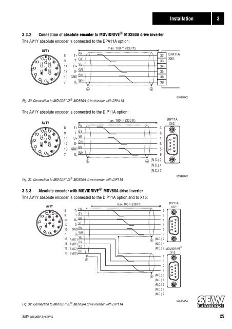
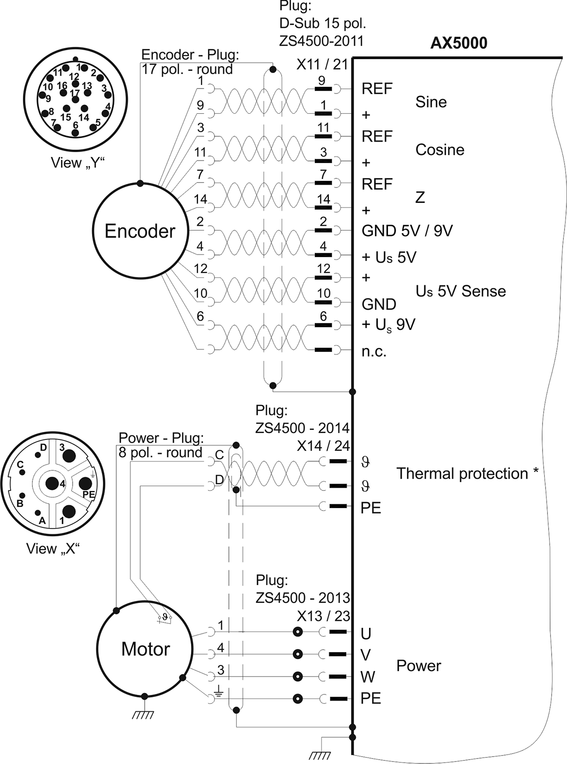
PepperlFuchs rotary Keep encoder wiring away from power cables and conduit If crossing The diagram below illustrates the output of a 3 channel Hohner Elektrotechnik GmbH was founded in in Werne an der Lippe, a of pulse encoders and its associated application possibilities. Absolute encoder SSI AV1Y ML 0 198 8 1 AS7Y2) 1 362 159 9 1 362 192 0 AV1Y 0 198 8 1 AG7Y2) 1 362 210 2 1 362 164 5 Absolute encoder Connection cable encoder connection cover → Ycable with connector for fixed installation. Absolute encoders transmit absolute position as a multibit digital word They can be connected using parallel wiring, fieldbus, or pointtopoint wiring The number of conductors needed for each type varies Learn more about absolute encoder communication protocols here Table 2 Absolute encoder wiring schemes Importance of Encoder Cable Quality.
Easy connection of sensors Cables/plugs IOLink Master Wireless IOLink master and app USB IOLink master Solutions Clean in place (CIP) Dairy Industrial encoders absolute Absolutely universal – reliable position feedback without referencing, singleturn and multiturn technology. Absolute encoder SSI AV1Y ML 0 198 8 1 AS7Y2) 1 362 159 9 1 362 192 0 AV1Y 0 198 8 1 AG7Y2) 1 362 210 2 1 362 164 5 Absolute encoder Connection cable encoder connection cover → Ycable with connector for fixed installation. Encoders you can use with the module module specifications The absolute encoder module is usually used for absoluteposition feedback highspeed response to position based on encoder values immunity to loss of position from power loss or power interruptions The Absolute Encoder Module (cat no 1771DE) is an intelligent module.
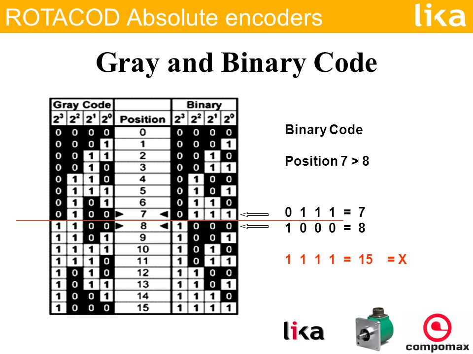
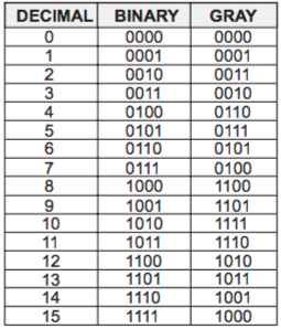
Collection of bei encoder wiring diagram A wiring diagram is a simplified standard photographic depiction of an electric circuit It reveals the parts of the circuit as streamlined forms, and the power and signal connections between the gadgets. Sensing element and support components are in the bottom Gray codes are used in linear and rotary position encoders ( absolute encoders and quadrature encoders ) in preference to weighted binary encoding. Optical Encoders K Craig 7 Schematic Diagram of an Absolute Encoder Disk Pattern (a) Binary code (b) Gray code In Binary Code, bit switching may not take place simultaneously Ambiguities in bit switching can be avoided by using gray code However, additional logic is needed to covert the graycoded number to a corresponding binary number.
Connection Type Common (0V) V Output Set 1 Set 2 Cable WH BN GN GY PK M12 pin 3 1 2 4 5 Wiring Diagram Male encoder view Mating cordset RKC 45T*/S618 * Length in meters 1⁾ = when the power supply is correctly applied Absolute, Multiturn Type RM97 (Shaft) / RM98 (Blind Hollow Shaft) Analog Click for Table of Content. 4 Connection an Absolute Encoder The encoder is connected by a 4 pin A coded M12 connector for the power supply and two 4 pin, Dcoded M12 connector for Ethernet 41 2Connector Ethernet Powerlink 4 pin female, Dcoded Pin Number Signal Sketch on encoder view 1 Tx 2 Rx 3 Tx 4 Rx 42 Connector Power Supply. Absolute Rotary Encoder Safety 3 Safety 31 Symbols Relevant to Safety 32 Intended Use Absolute rotary encoders detect the rotation angle —and, in the case of a multiturn absolute rotary encoder, the revolutions of the rotary encoder shaft—with high precision and resolution.
A rotary encoder, also called a shaft encoder, is an electromechanical device that converts the angular position or motion of a shaft or axle to analog or digital output signals There are two main types of rotary encoder absolute and incremental The output of an absolute encoder indicates the current shaft position, making it an angle transducer. R Absolute Rotary Encoder E6CN Ideal for Stepping Motor Tripping Detection and Position Control of Loaders or Unloaders H No need to reset origin point at powerup H IP50 certification H Ideal for packaging, plastics, electronics assembly, robotic and semiconductor. A rotary encoder is a position sensor used to determine the angular position of a rotating shaft It can be used with an Arduino through modules to achieve such functionality With two main types of rotary encoder available (Absolute encoder and Incremental encoder) that adopt different functional technologies, one would beg to wonder how does all of them work?.
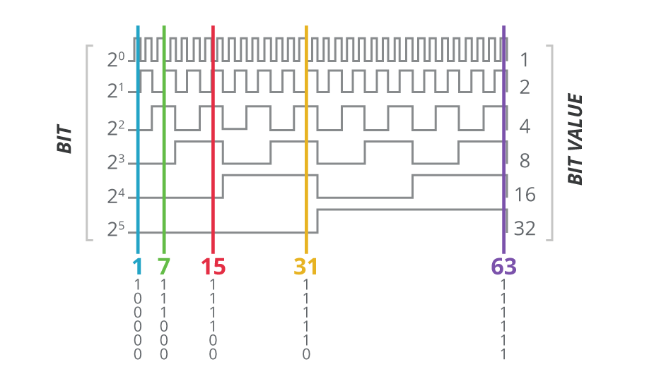
InstallationInstructions Bulletin842A Absolute Encoders IMPORTANT SAVE THESE INSTRUCTIONS FOR FUTURE USE Specifications Electrical CodeFormat Gray orNatural Binary CodeDirection CW or CCW Symmetry 40% to 60% Operating Voltage 10–32V DC Power Requirements 150mA @ 5V (no load) Max #ofSteps/Revolution 8192 Max # ofRevolutions 8192 Position Forming Time 05msec Delay on Power Up 1050msec. The output of absolute encoders is relative to its position in a form of a digital word Instead of a continuous flow of pulses as seen by incremental encoders, absolute encoders output a unique word for each position in form of bits Equivalent to 1,024 pulses per revolution, an absolute encoder is described to have 10 bits (210 = 1024). SEWEURODRIVES, you can order the encoders without a connection cover because this cover is already part of the prefabricated cable Encoder connection When connecting the encoders to the invert ers, always follow the operating instructions for the relevant inverter and the wiring diagrams supplied with the encoders.
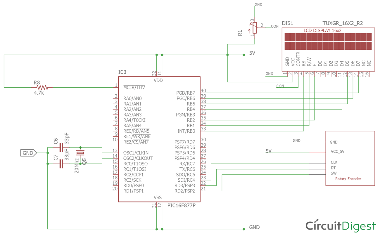
Rotary Encoder Interfacing With Pic Microcontroller Pic16f877a

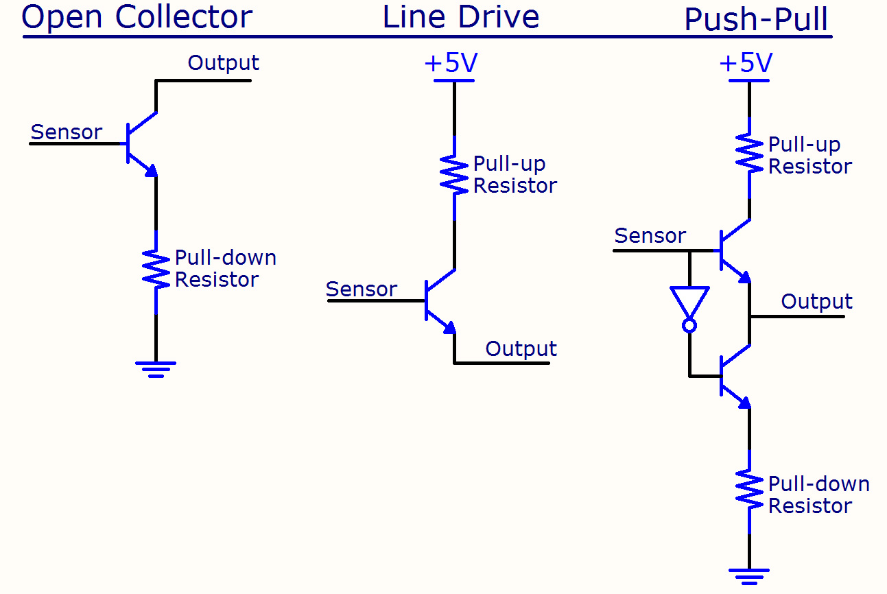
Incremental Encoder Signals Htl Push Pull Or Ttl Rs422

In Depth How Rotary Encoder Works And Interface It With Arduino
Incremental Rotary Encoders With Raspberry Pi Lpd3806 600bm Aleksandar Haber
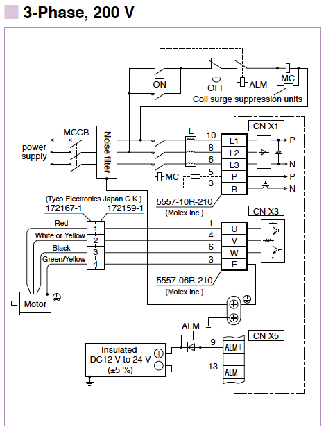
Minas E Series Wiring Connection Automation Controls Industrial Devices Panasonic
1
How To Use A Rotary Encoder In An Mcu Based Project Projects
Frequently Asked Questions
Ssi Encoders Encoder Interface Protocols Dynapar

Feedback Connections Titan
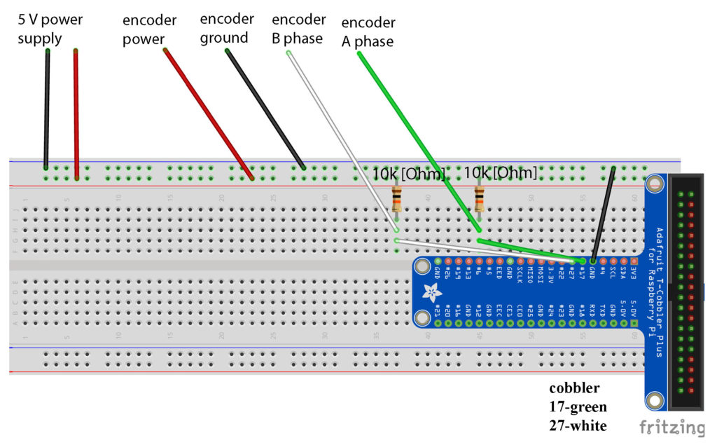
Interfacing An Absolute Encoder With Raspberry Pi Haresh Karnan
Encoder 7 Pole Wiring Diagram Jeep Cherokee Fuse Diagram For 0 Code 03 Asyikk Masuk1 Waystar Fr
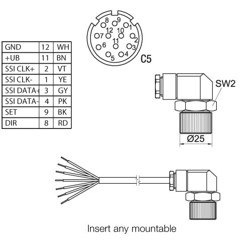
Wachendorff Automation Encoders Female Connector Kd 12 67 Suitable For Encoder Absolute Ssi With Connector Outlet C5 12 Pin Ip67

Uttih Bfk Absolute Position Encoder Yaskawa Sgmgv 09adc61 Ac Motor Encoder For Sale Servo Motor Encoder Manufacturer From China

Rotary Encoder Connection Wiring With Vfd Ac Drive Dc Drive Encoder Checking Method ह द म Youtube
Absolute Rotary Encoder Results In Serial Output Noise

Encoder Wiring Diagram Page 1 Line 17qq Com

P Series Cables Encoder Cable Color Code And Specs Electromechanical Knowledge Base Electromechanical Group Parker Community
Servo Motor Glossary Of Terms
32 Sew Encoder Wiring Diagram
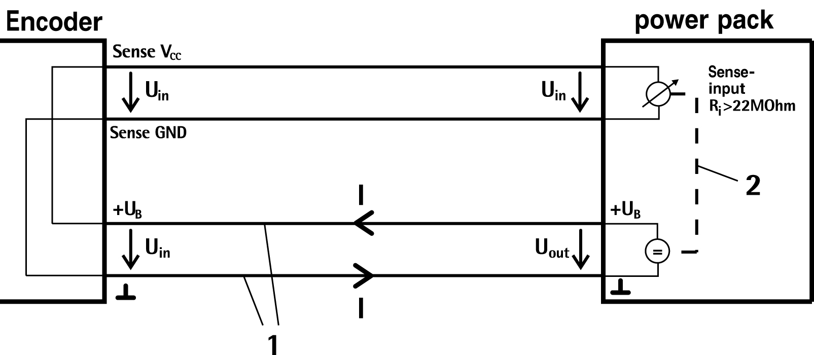
Voltage Monitoring Sense With 5v Encoder Hengstler Gmbh
Basics Of Rotary Encoders Overview And New Technologies Machine Design
Www Nidec Netherlands Nl Media 3956 Engineering Documentatie Technical Guide Leroy Somer Speed And Position Feedback Devices En 1810 A 5664a Pdf
Q Tbn And9gcq1ok0kntlxbeluitjkbfq5lcgd2i9visihdf0j78mynvndstao Usqp Cau
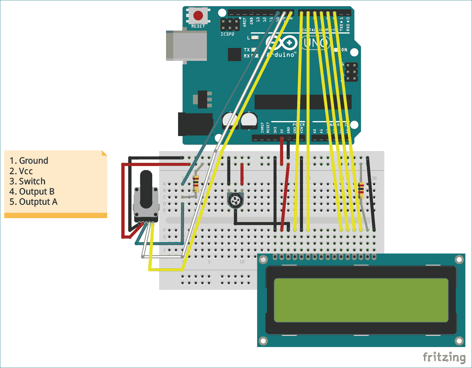
What Is Rotary Encoder And How To Use Ky 040 Rotary Encoder With Arduino
2

Encoder With Arduino Rotary Encoder Absolute Encoder Incremental Optical Encoder Encoder With Arduino Electronic Clinic
Encoders Explained Library Automationdirect Com
25 Sew Eurodrive Encoder Wiring Sew At Home

E Programming Cable For Absolute Encoder Rm Eclass 27 27 92 01

Feedback Connections Jupiter

Pin Assignment Simatic S7 1500 Tm Posinput 2 Id Industry Support Siemens

Rotary Encoders Further Information Technical Guide India Omron Ia
Tamagawa多摩川编码器说明书 日本tamagawa多摩川电机中文选型资料
Incremental Encoder Signals Htl Push Pull Or Ttl Rs422

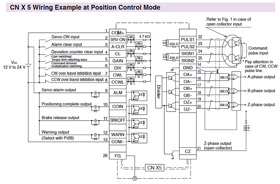
Wiring Diagrams Panasonic Weihong Doc
Rotacod Absolute Encoder Ppt Video Online Download
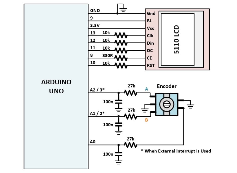
Arduino Project 4

Feedback Connections Jupiter

Wiring Diagrams Wise Weihong Doc
Multiwingspan

As5040 10 Bit Rotary Position Sensor With Absolute And Incremental Outputs Ams Ams
Www Nidec Netherlands Nl Media 3956 Engineering Documentatie Technical Guide Leroy Somer Speed And Position Feedback Devices En 1810 A 5664a Pdf

Feedback Connections Triton

As5030 8 Bit Absolute Contactless Rotary Position Sensor Ams Ams
Www Kuebler Com Pdf Pbs Basics Encoder 15 En Pdf
Stevenengineering Com Tech Support Pdfs 46kubler Pdf

Assembly Instructions Draw Wire System Szg93 With Incremental Encoder Wdg 40z Wachendorff Automation Gmbh Co Kg Pdf Catalogs Technical Documentation Brochure

Rotary Encoder Absolute Encoder Av30
Www Nidec Netherlands Nl Media 3956 Engineering Documentatie Technical Guide Leroy Somer Speed And Position Feedback Devices En 1810 A 5664a Pdf
Sick Absolute Encoder Made In Germany Atm60 Atm90 Absolute Encoders Singleturn Or Multiturn View Ssi Absolute Encoder Sick Product Details From Shanghai Qiyi Electrical Mechanical Equipment Co Ltd On Alibaba Com

Wiring The Rotary Encoder With Arduino 14core Com
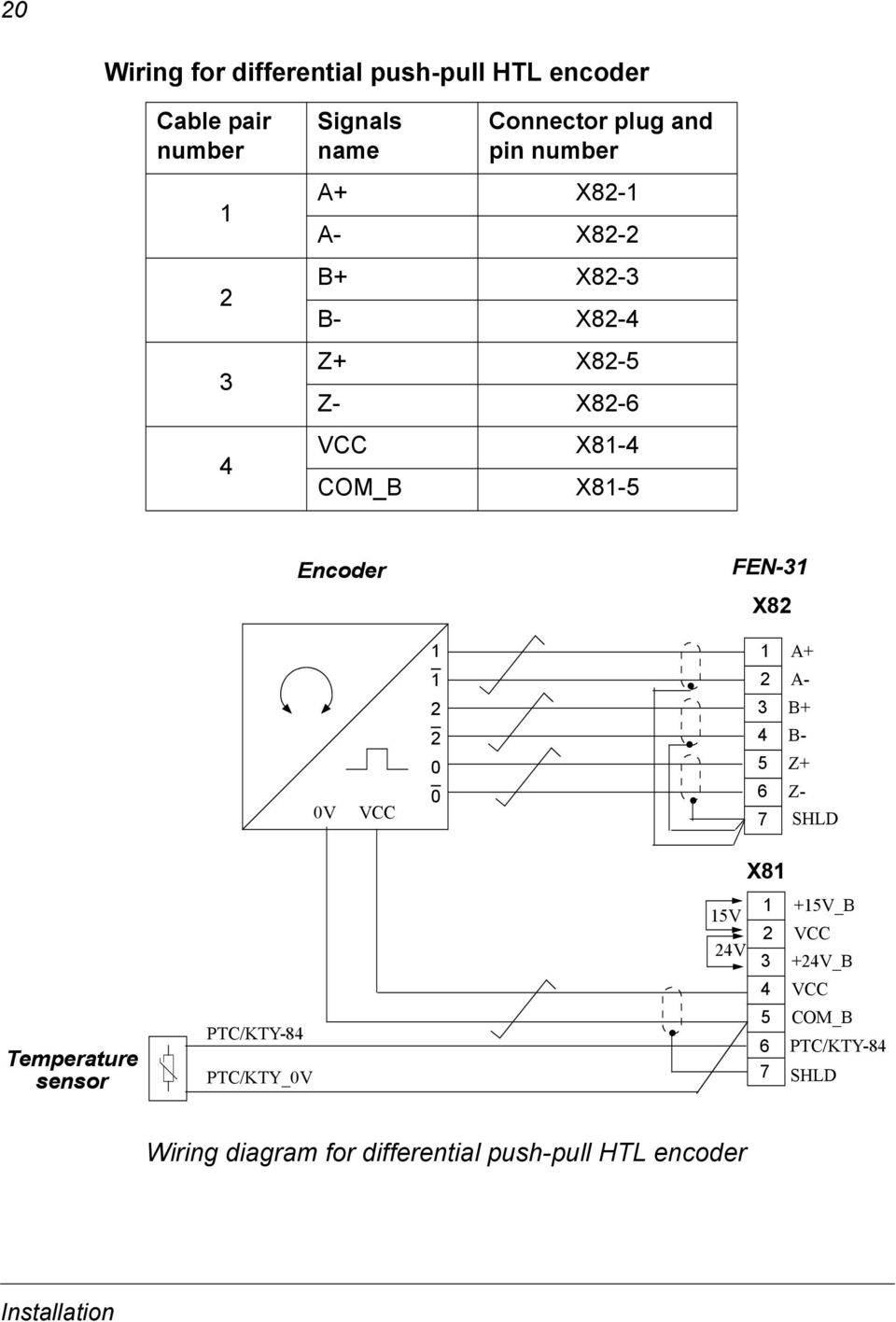
Abb Drives User S Manual Htl Encoder Interface Fen 31 Pdf Free Download
1
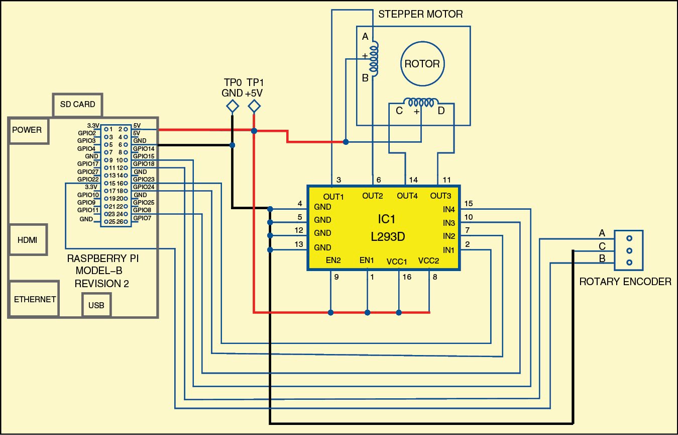
Controlling Stepper Motor Using Rotary Encoder Full Project Available

Feedback Connections Triton
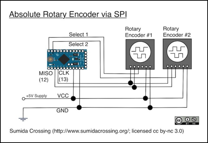
Arduino Knobs Electronics Basics Sumida Crossing
Encoder Primer Phidgets Support

Capacitive Absolute Encoders Cui Devices

Wiring Diagrams Panasonic Weihong Doc
Diagram Bei Encoder Wiring Diagram Full Version Hd Quality Wiring Diagram Reddiagram17 Ritmicavco It
When Is An Absolute Encoder Right For Your Design Cui Devices

Bourns Eaw Absolute Contacting Encoder Connection Diagram Download Scientific Diagram
Frequently Asked Questions

Rotary Encoders Further Information Technical Guide Australia Omron Ia
What Is A Rotary Incremental Encoder And Hall Effect

What Is Ttl Output For Incremental Encoders Motion Control Tips

Lika Electronic Incremental And Absolute Rotary Encoders Catalog 13 Edition In English By Lika Electronic Issuu

Draw Wire Encoders Kubler Group Worldwide
Support Industry Siemens Com Cs Attachments Geberparametrierung V1d0 En Pdf
Faq What Are The Ways To Wire An Absolute Encoder Into A Motion System

How To Use Rotary Encoder With Arduino Full Guide
Encoders Optical And Magnetic Incremental And Rotary

Feedback Connections Nix
Haas Encoder Wiring Diagram Wiring Diagram Encoder Wire Diagram Word Pamphlet Template Network Sick Absolute Encoder Made In Germany Atm60 Atm90 Absolute Sg31 Wire Actuated Encoder Siko Bei Encoder Pin Wiring Diagram

What Is Ttl Output For Incremental Encoders Motion Control Tips
Incremental Encoder Wikipedia
Library E Abb Com Public 2465a8f81ecb8ee1c1257dafce 2tlc1706m06 A Pdf
Basics Of Rotary Encoders Overview And New Technologies Machine Design

Using Encoders In Motion Control Automated Motion Systems Pty Ltd Australia

Incremental Encoder Wiring Diagram 00 Mustang Under Hood Fuse Box Diagram Begeboy Wiring Diagram Source

Feedback Connections Jupiter

Rotary Encoders Further Information Technical Guide India Omron Ia
Beckhoff Information System English
Arduino Project 4
.jpg)
Myomron Europe Myknowledge

Wiring Diagrams Wise Weihong Doc
Www Ti Com Lit Pdf Tiduan5
Linear Encoder Wiring Diagram 5 Wire 1977 Ford Wiring Harness Landrovers Yenpancane Jeanjaures37 Fr
Encoders Optical And Magnetic Incremental And Rotary

Rotary Encoders Further Information Technical Guide Australia Omron Ia

Encoders Basic Training Ppt Download
Rotary Encoder Pinout Features Circuit And Working

Position Sensor And Linear Positional Sensors
Bourns Eaw Absolute Contacting Encoder Connection Diagram Download Scientific Diagram

Incremental Encoder An Overview Sciencedirect Topics
Connection Diagram For Incremental Encoder Siemens 6fx 01 2 Up 5v Rs 422 Simat Id Industry Support Siemens

Diagram Haas Encoder Wiring Diagram Full Version Hd Quality Wiring Diagram Hydradiagrams Orologireplicastore It


