High Voltage Amplifier Circuit
The High Voltage Input Fet Power Amplifier Circuit Diagram Amplifier Circuits Audio Amplifier Circuit Circuit Diagram Seekic Com

Figure 1 From A High Voltage Class D Power Amplifier With Switching Frequency Regulation For Improved High Efficiency Output Power Range Semantic Scholar
An7062n 1539 Pdf Datasheet Download Ic On Line
Op Amp Practical Considerations Operational Amplifiers Electronics Textbook

Low Voltage Audio Amplifier

Bootstrapping A Low Voltage Op Amp To Operate With High Voltage Signals And Supplies Analog Devices
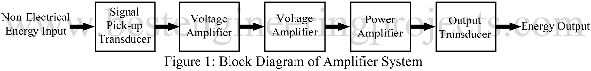
There are different designs in power amplifiers for different requirements of W, 50W and 100W of RMS value A power amplifier circuit consists of unique circuit to produce voltage and power gain This consists of three amplification stages, namely Voltage amplification stage;.

High voltage amplifier circuit. APEX P3 ZIP12 HIGH VOLTAGE POWER OPERATIONAL AMPLIFIERS;. It can be pulled to the negative supply rail to disable the amplifier The voltage on this pin can also be monitored to check the status of the amplifier Any monitoring circuit should have an input impedance of greater than 0 kOhm A high level voltage on the enable pin indicates a normal status while a low level indicates a thermal shutdown The recommended enable circuits for unipolar and bipolar supplies are shown below. APEX P3 ZIP12 HIGH VOLTAGE POWER OPERATIONAL AMPLIFIERS;.
Bridge Amplifier The circuit given below is a bridge audio amplifier circuit using IC TD935 Description TD935 is 2x15W high quality audio amplifier IC from Siemens The. A conventional high voltage amplifier at certain capacitive loading conditions are eliminated Example with numbers, using the Falco Systems WMA300 high speed, high voltage amplifier In the following section, we illustrate the principles discussed above by comparing them to specs of a real high voltage amplifier, the Falco Systems WMA300 (Fig 9). APEX P3 ZIP12 HIGH VOLTAGE POWER OPERATIONAL AMPLIFIERS Minimum Quantity Starting from one lot Product Attributes Categories Electronic Components & Supplies;.
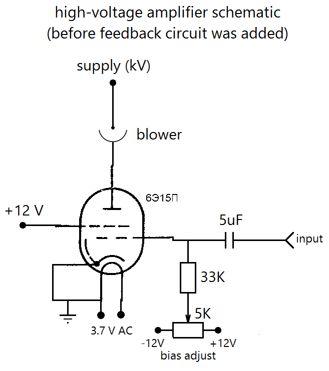
Re High voltage AC amplifier (quick, dirty circuit) « Reply #10 on November 23, 13, am » Try a small toroidal as the inverter transformer, they have a much wider frequency response. The TD498E amplifier offers flexible audiosystem configuration, in both stereo and mono modes, and also includes the mono parallel feature for driving the subwoofer/woofer channel in 21 sound setups To maximize the speaker output power, soundsystem manufacturers require highefficiency amplifiers capable of driving speakers at low impedances of 2 or 3 ohms, which creates a challenge by. A voltage amplifier in simplest form is any circuit that puts out a higher voltage than the input voltage When you are forced to work with a set amount of voltage, these amplifiers are commonly used to increase the voltage and thus the amount of power coming out of a circuit.
The Small Signal Amplifier is generally referred to as a “Voltage” amplifier because they usually convert a small input voltage into a much larger output voltage Sometimes an amplifier circuit is required to drive a motor or feed a loudspeaker and for these types of applications where high switching currents are needed Power Amplifiers are. High voltage, highside floating current sensing circuit using current output current sense amplifier Lowdrift, lowside, bidirectional current sensing circuit with integrated precision gain resistors. The secondary of the highvoltage transformer needs to be /0mA, or close to this, for a fullwave capacitor input supply Powersupply design is as hotly debated as amplifier design itself.
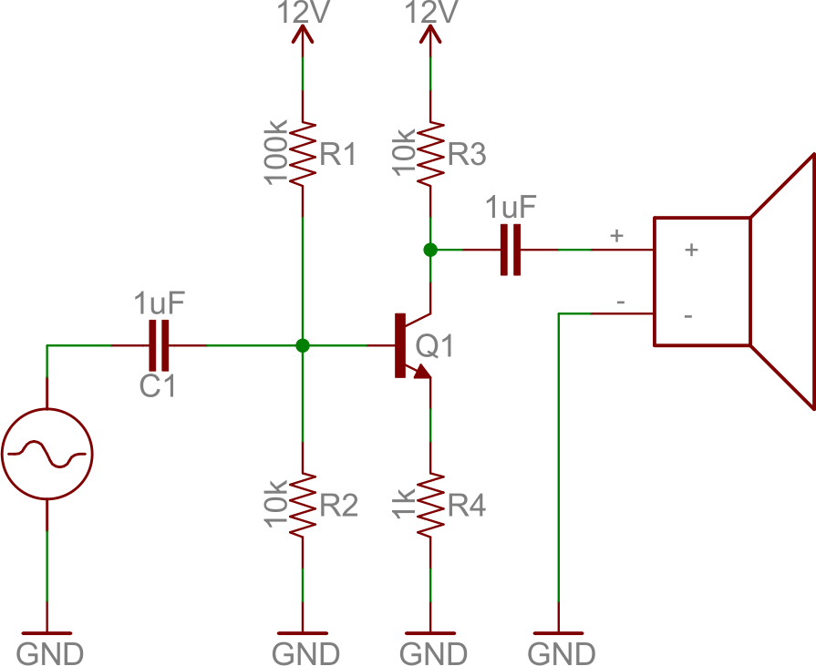
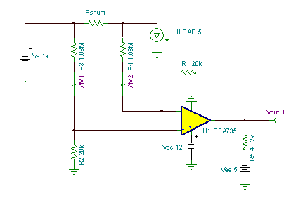
Tube amplifiers can benefit from regulated and stabilized power supplies, especially sensitive preamplifier stages, but also (singleended) power amps But traditional highvoltage regulators add several extra tubes, complexity, and power losses, while good performance is not easy to obtain. Designing a high voltage gain amplifier So let us start designing for the circuit shown in figure 1 We pick the transistor BC109, as it is having hfe around 300. A voltage amplifier circuit is a circuit that amplifies the input voltage to a higher voltage So, for example, if we input 1V into the circuit, we can get 10V as output if we set the circuit for a gain of 10 Voltage amplifiers, many times, are built with op amp circuits However, with a transistor and the correct biasing, we can produce the same voltage amplification effect of an op amp circuit.
Product id sku 2bd3a1b012d911ea91a0001c4299 gtin14 mpn 38f. This is a Protection circuit from high voltage to any device by the automatic cutoff using popular ic 741 Note Connect the load with NC pin of the relay When the input voltage at Non inverting pin of opamp 741 is cross over the set reference voltage. Current sense amplifiers (150) Current sense amplifiers analog output (130) Current/voltage/power monitors () Difference amplifiers (29) Fully differential amplifiers (64) Instrumentation amplifiers (53) Operational amplifiers (op amps) (1525) Audio op amps (66) Generalpurpose op amps (769) Highspeed op amps (GBW>=50MHz) (336) Power op amps.
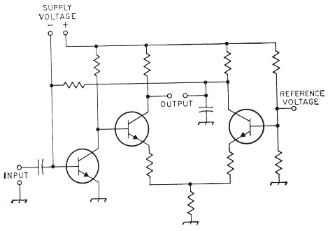
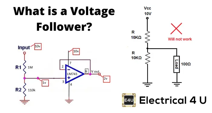
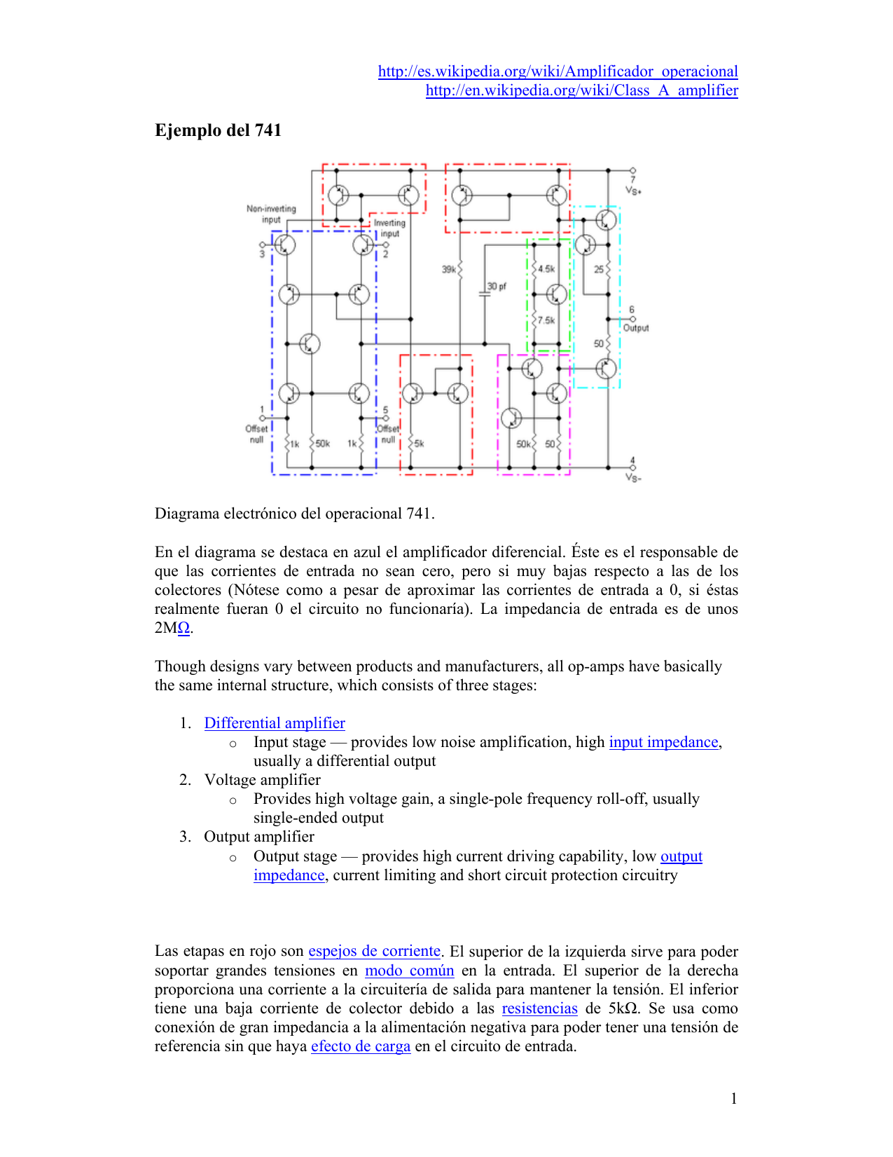
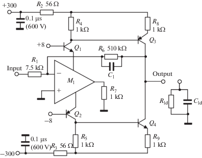
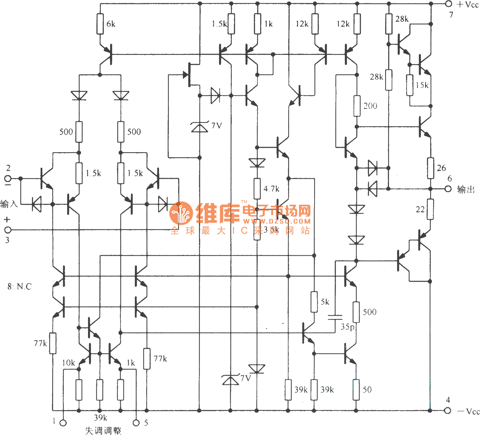
Voltage buffer A voltage buffer amplifier is used to transfer a voltage from a first circuit, having a high output impedance level, to a second circuit with a low input impedance level The interposed buffer amplifier prevents the second circuit from loading the first circuit unacceptably and interfering with its desired operation, since without the voltage buffer the voltage of the second. CE Amplifier Frequency Response The voltage gain of a CE amplifier varies with signal frequency. Amplifier, and is not essential to the initial description of operation The basic circuit uses a differential input since this connection is mandatory for low drift and high commonmode rejection ratio Two commonemitter stages (transistors Q3 and Q4) are used to provide the high voltage gain.
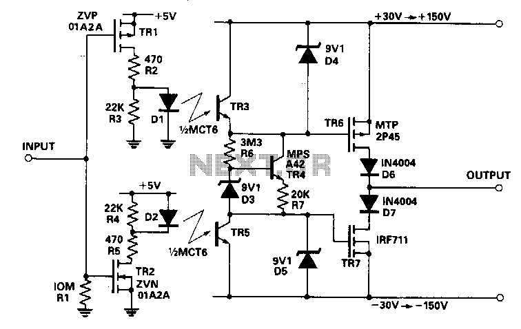
If you have an amp that takes more than a couple of amps, you probably operate a transmitter and even then, no sweat!. Highvoltage drive is useful for driving electrodes in many applications The challenge is to boost the output of a conventional op amp to high voltages Available ac highvoltage amplifier modules are limited to approximately 10V pp This Design Idea presents a simplified ac highvoltage amplifier that uses complementary, cascaded NMOS and PMOS transistors (Figure 1) The OP07 op amp has low inputoffset voltage, low inputbias current, and high openloop gain. Subwoofer Amplifier Circuit Theory Audio Signal is initially filtered in order to eliminate the high frequency content and enable just the lower frequencies to cross via it This specific lower frequency transmission can now be amplified by using a voltage amplifier.
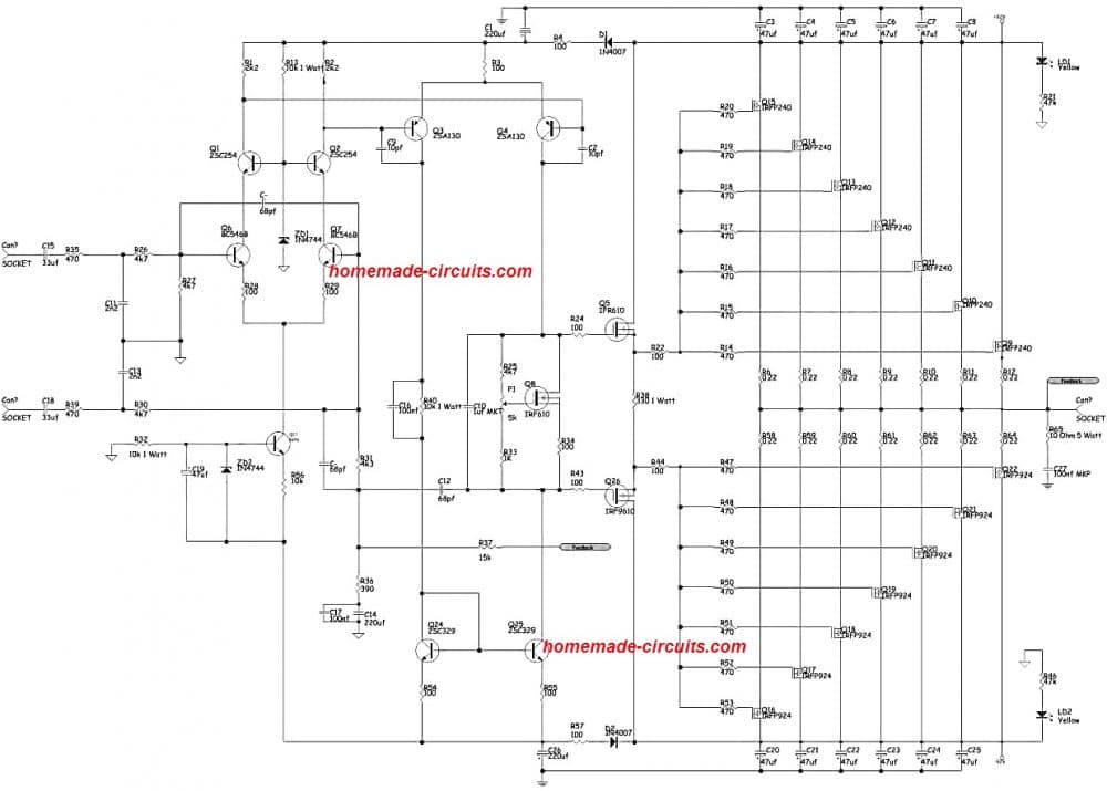
High Voltage, High Efficiency MOSFET RF Amplifiers – series RLC circuit The C is the specified Ciss from the data sheet at the desired operating supply voltage The R is the effective series resistance, ESR, of Ciss and includes dielectric losses, gate metalization (or. This power amplifier circuit is a 1600W at 8 Ohm mono circuit that uses transistors as an amplifier Almost same with 2800W high power amplifier circuit, For stereo power amplifier circuit, you can use this circuit 2x and will issue a power of 30W Let us first see the circuit schematic below 1600W High Power Amplifier Circuit Diagram. Biasing an amp requires some knowledge of tube amp circuits and experience with high voltage If you are uncertain that you are experienced enough to work on a live high voltage amp, please take your amp to a professional to get it biased This calculator uses the power equation P = I × V.
Introduction to Operational Amplifiers An op amp is a voltage amplifying device With the help of some external components, an op amp, which is an active circuit element, can perform mathematical operations such as addition, subtraction, multiplication, division, differentiation and integration If we look at a general op amp package (innards to come in a later tutorial) such as the. A voltage follower (also known as a buffer amplifier, unitygain amplifier, or isolation amplifier) is an opamp circuit whose output voltage is equal to the input voltage (it “follows” the input voltage) Hence a voltage follower opamp does not amplify the input signal and has a voltage gain of 1. APEX P3 ZIP12 HIGH VOLTAGE POWER OPERATIONAL AMPLIFIERS;.
These transducers require highvoltage and widebandwidth amplifiers The basis of the circuit in Figure 1 is an earlier Design Idea (Reference 1) The operation of the circuits is basically the same, but this one can drive a 23nF capacitive load at frequencies as high as 500 kHz In this circuit, an LM7171 op amp from National Semiconductor replaces the LF411, also from National Semiconductor, of the earlier design The LM7171 op amp has a unitygain bandwidth of 0 MHz. High Voltage Amplifiers Our extensive line of Trek high voltage amplifiers offer numerous voltage and current ranges to accommodate your demanding applications Protect against output short circuits and overvoltages For protective shutdown, utilize automatic crossover compliance limits or current trip features. This power amplifier circuit is a 1600W at 8 Ohm mono circuit that uses transistors as an amplifier Almost same with 2800W high power amplifier circuit, For stereo power amplifier circuit, you can use this circuit 2x and will issue a power of 30W Let us first see the circuit schematic below 1600W High Power Amplifier Circuit Diagram.
Voltage buffer A voltage buffer amplifier is used to transfer a voltage from a first circuit, having a high output impedance level, to a second circuit with a low input impedance level The interposed buffer amplifier prevents the second circuit from loading the first circuit unacceptably and interfering with its desired operation, since without the voltage buffer the voltage of the second. Circuit voltage gain, Av = hfe/hie*(Rc RL) Circuit current gain, AI = hfe RC Rb/ (RcRL) (Rchie) Circuit power gain, Ap = Av * Ai;. Tube amplifiers can benefit from regulated and stabilized power supplies, especially sensitive preamplifier stages, but also (singleended) power amps But traditional highvoltage regulators add several extra tubes, complexity, and power losses, while good performance is not easy to obtain This article, published in audioXpress, April 09, describes a novel design that is very simple yet offers excellent performance.
Max high voltage supply current that can be switched has no practical limit;. A capacitive load at the output of the high voltage amplifier can change its slew rate Instabilities and overshoot due to capacitive loading Many high voltage amplifiers have an internal circuitry that looks like a high voltage version of the general operational amplifier (opamp, Fig 6) A capacitor at the output of such a circuit in. The DC bias circuit sets the DC operating “Q” point of the transistor and as the input capacitor, C1 acts as an open circuit and blocks any DC voltage, at DC (0Hz) the input impedance (Z IN) of the circuit will be extremely high However when an AC signal is applied to the input, the characteristics of the circuit changes as capacitors act as short circuits at high frequencies and pass AC signals.
Voltage circuits, as well as various other connections for power and online switching, high voltage metering, plate current trip and reset circuits, indicator lamps, and so forth The high voltage connection to each RF deck is made through a shielded length of RG6/U coaxial cable, using special high voltage BNC connectors rated at 5000 working volts For safety purposes, the. Net result, an amplifier with up to 600v output swing, but at managed current (programmed by R3 mostly), so that you can control the heat High voltage stages like this can easily overheat unless you plan dissipation carefully heatsinking likely to be needed Some detailed attention required to the thermal design Quite an elegant design. But in most applications, common emitter and common collector amplifier circuits generally have high input impedances Some types of amplifier designs, such as the common collector amplifier circuit automatically have high input impedance and low output impedance by the very nature of their design.
At the time of amplifier circuit stanby, measure voltage contained in the R19 or R resistors and set at 150mV This high power audio amplifier circuit designed for high power amplification to provide peak power 2kW and 1,5kW continuously, so that this amplifier can drive your big speakers with fantastic. Current sense amplifiers (150) Current sense amplifiers analog output (130) Current/voltage/power monitors () Difference amplifiers (29) Fully differential amplifiers (64) Instrumentation amplifiers (53) Operational amplifiers (op amps) (1525) Audio op amps (66) Generalpurpose op amps (769) Highspeed op amps (GBW>=50MHz) (336) Power op amps. APEX P3 ZIP12 HIGH VOLTAGE POWER OPERATIONAL AMPLIFIERS Minimum Quantity Starting from one lot Product Attributes Categories Electronic Components & Supplies;.
APEX P3 ZIP12 HIGH VOLTAGE POWER OPERATIONAL AMPLIFIERS Minimum Quantity Starting from one lot Product Attributes Categories Electronic Components & Supplies;. This is a high impedance input 2 stage preamplifier that features an adjustable voltage gain, from 15 to 10 This gain can be varied by setting up VRI and becomes handy where the MIC sensitivity required to be varied often As shown above, the circuit is actually designed for crystal microphones or ceramic cartridges. Achieve maximum performance with highvoltage amplifiers Our highvoltage amplifiers provide a wide common mode range, high sensing capabilities and greater supply compatibility They enable dc precision down to 05 µV, bandwidth up to 8 GHz and wide commonmode range up to ±275V for a wide variety of industrial, automotive and communications systems, including HEV/EV, infotainment, factory automation, medical, motor drive, appliances, test and measurement, power delivery, and wireless.
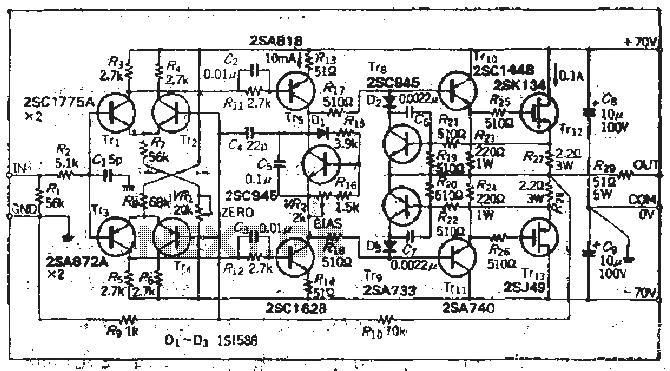
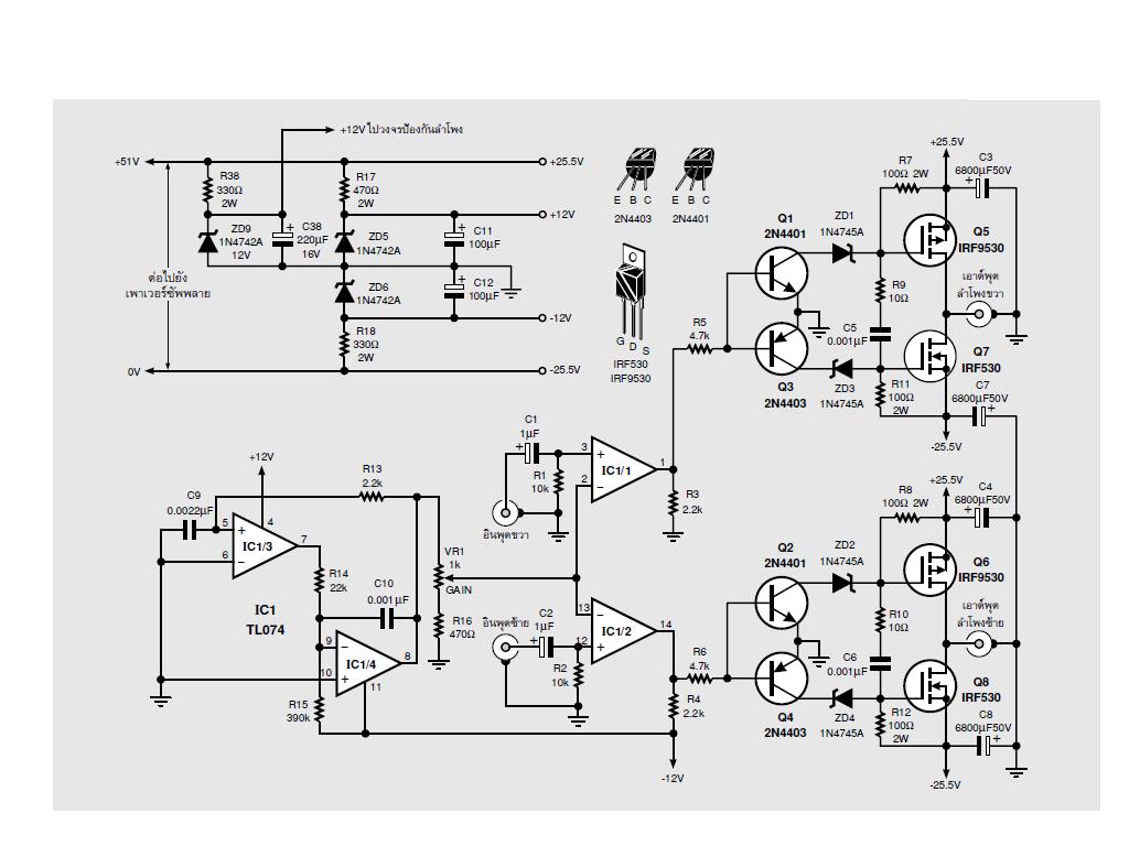
And you need to make sure that the capacitors that you are using for filtering are rated for high voltage, at least 100VAC (more doesn't hurt) The rest of the capacitors in the design also need to have an appropiate voltage rating I designed this amplifier for an output power of about W. The signal is amplified by the driver circuit consist of the Q7 (2SA640), Q8 (2SA640), Q9 (2SA690) to as the signal voltage is high enough to drive the output 2SK1058 MOSFET Q14, Q15, Q16, Q17 for acts as the positive signal to the speaker (2SJ162 MOSFET Q18, Q19, Q, Q21 for the negative signal). This circuit allows for the creation of a very high impedance input and low impedance output This is useful to interface logic levels between two components or when a power supply is based on a voltage divider The figure below is based on a voltage divider, and the circuit cannot function.
It is useful in a wide variety of applications requiring high output voltage or large commonmode voltage swings The OP45's high slew rate provides wide powerbandwidth response, which is often required for highvoltage applications FET input circuitry allows the use of highimpedance feedback networks, thus minimizing their output loading effects Laser trimming of the input circuitry yields low input offset voltage and drift. Product id sku 2bd3a1b012d911ea91a0001c4299 gtin14 mpn 38f. Highvoltage amplifier uses simplified circuit JuiI Tsai, JunMing Shieh, TaiShan Liao, and ChingCheng Teng, National Chiao Tung Unversity, Taiwan This ac highvoltage amplifier can deliver more than 1800V pp The sinusoidal input is 8V pp (top trace), and output is 1800V pp (bottom trace) Figure 2 The input is 750.
The voltage gains of the Figure 3 circuits depend on the individual opamp openloop voltage gains, and these are subject to wide variations between individual devices One special application of the 'openloop' opamp is as a differential voltage comparator, one version of which is shown in Figure 4(a)Here, a fixed reference voltage is applied to the inverting terminal and a variable test or. Product id sku 2bd3a1b012d911ea91a0001c4299 gtin14 mpn 38f. An operational amplifier (often op amp or opamp) is a DCcoupled highgain electronic voltage amplifier with a differential input and, usually, a singleended output In this configuration, an op amp produces an output potential (relative to circuit ground) that is typically 100,000 times larger than the potential difference between its input terminals.
Voltage buffer A voltage buffer amplifier is used to transfer a voltage from a first circuit, having a high output impedance level, to a second circuit with a low input impedance level The interposed buffer amplifier prevents the second circuit from loading the first circuit unacceptably and interfering with its desired operation, since without the voltage buffer the voltage of the second. Re High voltage AC amplifier (quick, dirty circuit) « Reply #10 on November 23, 13, am » Try a small toroidal as the inverter transformer, they have a much wider frequency response. The primary function of the voltage amplifier circuit is to raise the voltage level of the signal It is designed to achieve the largest possible gain Only very little power can be drawn from the output In order to achieve high voltage amplification the voltage amplifier circuit must fulfill following requirement.
High Voltage, High Efficiency MOSFET RF Amplifiers – series RLC circuit The C is the specified Ciss from the data sheet at the desired operating supply voltage The R is the effective series resistance, ESR, of Ciss and includes dielectric losses, gate metalization (or. Voltage buffer A voltage buffer amplifier is used to transfer a voltage from a first circuit, having a high output impedance level, to a second circuit with a low input impedance level The interposed buffer amplifier prevents the second circuit from loading the first circuit unacceptably and interfering with its desired operation, since without the voltage buffer the voltage of the second. This useful preamplifier circuit is an enhanced version of the above design It has a voltage gain which can be set at any level between five and one hundred times by using a feedback resistor of the appropriate value The input impedance is high, being typically about 800K and a low output impedance of around 1 ohms is obtained.
Current sense amplifiers (150) Current sense amplifiers analog output (130) Current/voltage/power monitors () Difference amplifiers (29) Fully differential amplifiers (64) Instrumentation amplifiers (53) Operational amplifiers (op amps) (1525) Audio op amps (66) Generalpurpose op amps (769) Highspeed op amps (GBW>=50MHz) (336) Power op amps. The second stage of transistor amplification, Q6, thus sees the high impedance collector circuit of Q3 as a constantcurrent souce and R4 / R5 deliver a highvoltage (butdefinedlowcurrent) swing, at the junction of R4 and R5;. The delay time default is 30 seconds and can be changed to any value, in 2 sec steps, between and 254 seconds Construction and article download.
Highvoltage amplifier uses simplified circuit JuiI Tsai, JunMing Shieh, TaiShan Liao, and ChingCheng Teng, National Chiao Tung Unversity, Taiwan This ac highvoltage amplifier can deliver more than 1800V pp The sinusoidal input is 8V pp (top trace), and output is 1800V pp (bottom trace) Figure 2 The input is 750. High voltage Protection circuit This is a Protection circuit from high voltage to any device by the automatic cutoff using popular ic 741 Note Connect the load with NC pin of the relay When the input voltage at Non inverting pin of opamp 741 is cross over the set reference voltage. And you need to make sure that the capacitors that you are using for filtering are rated for high voltage, at least 100VAC (more doesn't hurt) The rest of the capacitors in the design also need to have an appropiate voltage rating I designed this amplifier for an output power of about W You should use a bipolar power supply with ±30V.

0 Watt High Quality Audio Amplifier Circuit Diagram Audio Amplifier Hifi Amplifier Subwoofer Amplifier

Combining High And Low Voltage Circuits Digikey
High Voltage High Exchange Rate Power Amplifier Circuit Diagram Amplifier Circuit Circuit Diagram Seekic Com
1

High Voltage Ac Amplifier Quick Dirty Circuit
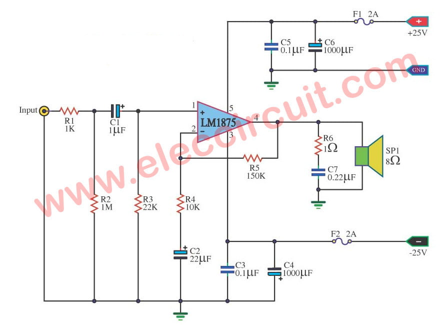
Lm1875 Datasheet 25w Hifi Audio Amplifier Circuit Eleccircuit Com
High Voltage Amplifier Circuit Diagram For Piezoelectric Ceramic Element Amplifier Circuit Circuit Diagram Seekic Com
High Gain Voltage Controlled Transistor Amplifier

Pin On Hubby Project

How To Build Motorola Hi Fi Power Amplifier Circuit Diagram

Edge

Experiment Transistor Circuit Design
A Besides Of Having High Voltage Gain State Two Chegg Com

Common Emitter Amplifier And Transistor Amplifiers

High Voltage Op Amplifier Circuit Analize Electrical Engineering Stack Exchange

An Integrated High Voltage Low Distortion Current Feedback Linear Power Amplifier For Ultrasound Transmitters Using Digital Predistortion And Dynamic Current Biasing Techniques Semantic Scholar
1
Sensors Free Full Text A High Voltage And Low Noise Power Amplifier For Driving Piezoelectric Stack Actuators Html
Index 565 Circuit Diagram Seekic Com

Robust High Voltage Over The Top Op Amps Maintain High Input Impedance With Inputs Driven Apart Or When Powered Down Analog Devices

Schematic Of The High Voltage Correction Amplifier Download Scientific Diagram

Electronic Devices Bjt Amplifiers Part 3
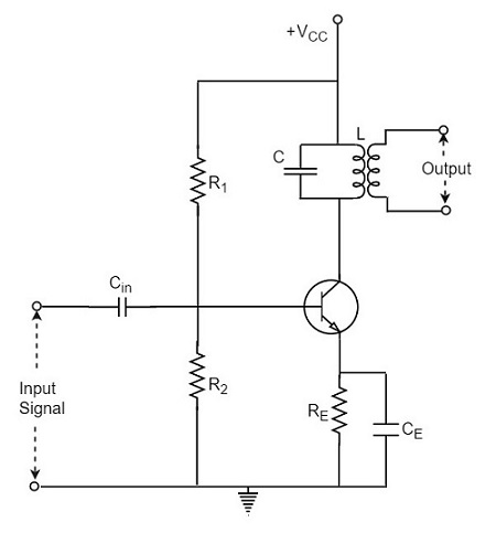
Tuned Amplifiers Tutorialspoint
High Voltage Op Amplifier Circuit Analize Electrical Engineering Stack Exchange
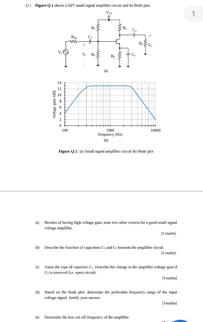
Solved Q 1 Figure Q 1 Shows A Bjt Small Signal Amplifier Chegg Com
Q Tbn And9gcs2bgdzmhavmg34h4jjwgi6wrq5wdrmjegrfpemp4oq3lxzz8q8 Usqp Cau
Pywugpy3 Jaipm

Class A Amplifier Is A Class A Transistor Amplifier

Figure 1 From A Cascaded Linear High Voltage Amplifier Circuit For Dielectric Measurement Semantic Scholar

Schematic Diagram Of The High Voltage Amplifier Circuit Each Printed Download Scientific Diagram

Experiment Transistor Circuit Design
How To Build A Voltage Amplifier Circuit With A Transistor
Low Voltage Transistor In High Voltage Current Amplifier Circuitlab
1000 Watt To 00 Watt Power Amplifier Circuit Homemade Circuit Projects

Epa1 An Audio Amplifier Google Patents

Simplified Schematic Of The Proposed High Voltage Amplifier Download Scientific Diagram

Cascaded Topology Of Linear High Voltage Amplifier Download Scientific Diagram
Circuit Diagram Of The High Voltage Amplifier The Main Feedback Loop Download Scientific Diagram
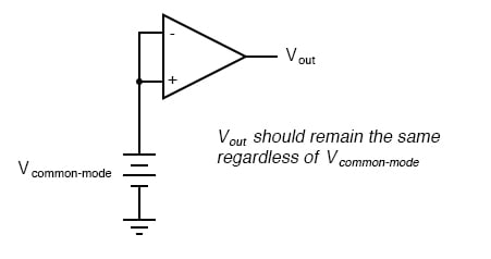
Creation And Simulation Of A High Common Mode Voltage Difference Amplifier Circuit Using Tinacloud The Circuit Design Blog

Operational Amplifier Circuit Diagram Principle And Debugging Analysis Electronic Paper

Is Possible To Give High Voltage To Amplifier Quora
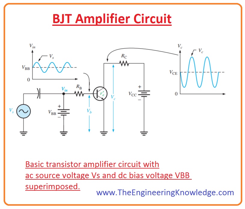
Bjt As An Amplifier The Engineering Knowledge

Amplifier Circuit Diagram Power Amplifier Voltage Amplifier

High Frequency Voltage Amplifier Opamp Keeps Clipping And Oscillating Electrical Engineering Stack Exchange
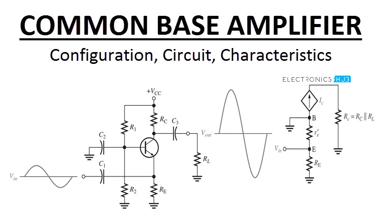
Common Base Amplifier Configuration Circuit Characteristics
High Voltage Circuit Page 2 Power Supply Circuits Next Gr

Voltage Amplifier 4 Steps Instructables

Pin On Industrial Instrumentation

Planet Analog Rarely Asked Questions Bootstrap A Low Voltage Op Amp To Operate With High Voltage Signals And Power Part 2

Pdf A Cascaded Linear High Voltage Amplifier Circuit For Dielectric Measurement

High Voltage Cmos Amplifier Enables High Impedance Sensing With A Single Ic Analog Devices
An7060 Pdf Datasheet Download Ic On Line

High Voltage Amplifier Uses Simplified Circuit Edn

Cascode Wikipedia
Amplifier Circuit Diagram Power Amplifier Voltage Amplifier
Results Page 73 About Modem Circuit Searching Circuits At Next Gr
Ejemplo Del 741 Manualzz
Intusoft Newsletter November 1999 Intuscop5 Beta New Icap 4 High Voltage Booster Amp Help On The Web Software Winners

Experiment Transistor Circuit Design
Simplify Your Bill Of Materials With High Voltage Amplifiers Analog Technical Articles Ti E2e Support Forums

Subwoofer Amplifier Circuit Diagrams Download Full Hd Version Diagrams Download Loth Diagram Simonebolelli It

Schematic Diagram Of The High Voltage Amplifier Circuit Each Printed Download Scientific Diagram

Help Me Understand This High Voltage Amplifier Circuit For Driving A Piezo Actuator Electrical Engineering Stack Exchange

Pdf A Cascaded Linear High Voltage Amplifier Circuit For Dielectric Measurement

Figure 1 From Efficiency Improved High Voltage Analog Power Amplifier For Driving Piezoelectric Actuators Semantic Scholar

High Voltage Amplifier Uses Simplified Circuit Edn

High Voltage Amplifier Drives Piezo Tubes Edn
Q Tbn And9gcrbidx0sp1sv02opmf4iwbxvqowhqubjhztaoc7pwyo42fpzvuj Usqp Cau

High Voltage Cmos Amplifier Enables High Impedance Sensing With A Single Ic Analog Devices
T Reg A High Voltage Regulator For Tube Amps Audioxpress
Www Ias Ac In Article Fulltext Sadh 033 05 0713 07

High Voltage Amplifier Uses Simplified Circuit Edn

Class A Amplifier Is A Class A Transistor Amplifier
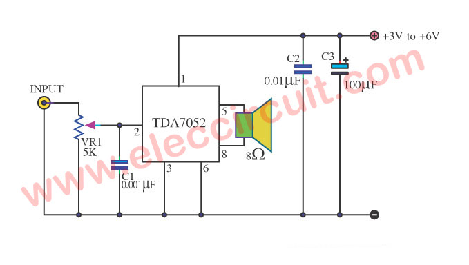
Tda7052 Amplifier Low Voltage 3v 5v 1 W Btl Amp
Transimpedance Amplifier Tutorial Working Design Applications
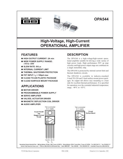
High Voltage High Current Operational Amplifier Opa544
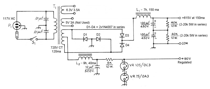
The 8v 6146b Amplifier Power Supply Schematic Diagrams And Circuit Descriptions
Iw High Voltage Amplifier Hackaday Io

High Voltage Amp Drives Piezoelectric Pvdf Transducer Ic Board Systems Design Edn Asia
A High Voltage Amplifier Springerlink

Digitally Gain Controlled Linear High Voltage Amplifier For Laboratory Applications Review Of Scientific Instruments Vol No 8
An Interesting Class D Amplifier Design Regulated 2v 2x60w Electronics Projects Circuits
High Voltage Ac Amplifier Quick Dirty Circuit

High Power Amplifier Circuit Diagram Circuit Diagram Images Circuit Diagram Power Amplifiers Audio Amplifier
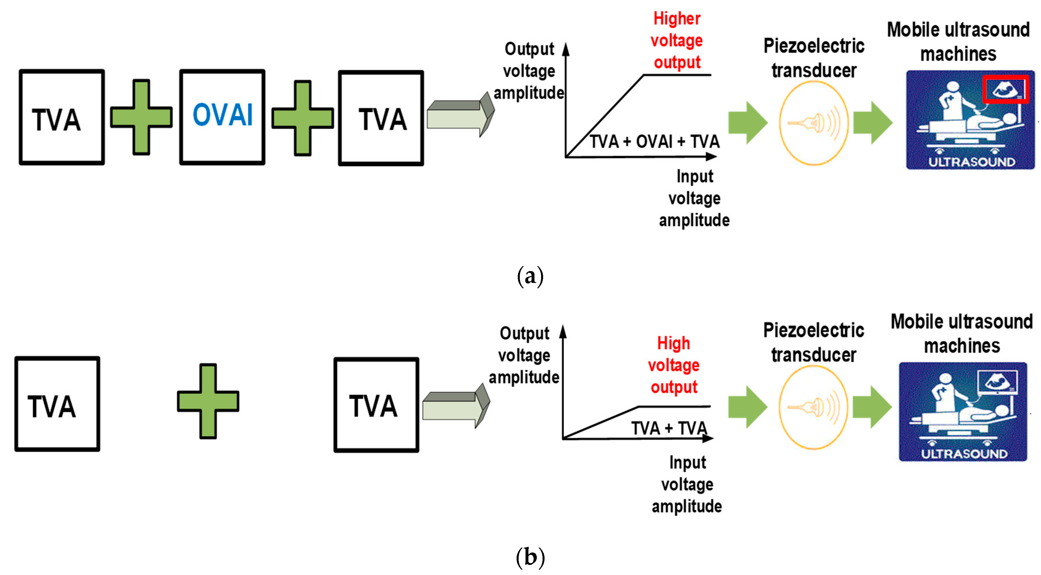
Sensors Free Full Text Inter Stage Output Voltage Amplitude Improvement Circuit Integrated With Class B Transmit Voltage Amplifier For Mobile Ultrasound Machines Html

High Voltage Regulator Schematic Circuit Diagram
Transistors Learn Sparkfun Com

Accurate And Fast 80mhz Amplifier Draws Only 2ma Analog Devices
Common Collector Amplifier Basic Electronics Tutorials

Pdf High Voltage Amplifier Designs For Penning And Radio Frequency Traps

Isolated High Voltage Amplifier Idea Electrical Engineering Stack Exchange

Planet Analog Buffer Amplifier Design
High Voltage Amplifier Circuit Board Card Model Pc 0213 01 Ebay

Using Low Voltage Drivers To Boost Rf Power Amplifier Efficiency Industry Articles
High Common Mode Voltage Difference Amplifier Blog The Circuit Design Blog
High Voltage Operational Amplifier Circuit With Internal Compensation Amplifier Circuit Circuit Diagram Seekic Com

A Paul Kemble Web Page Mission Cyrus 1 Integrated Amplifier
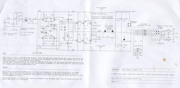
How To Build 5 000w Ultra Light High Power Amplifier Without Switching Mode Power Supply Circuit Diagram


